Automated power optimization: autofocus for optical networks

On 28 April 1985, the New York Times praised autofocus, a novel breakthrough in photography that has since redefined the way humans interact with memories. Before autofocus, taking a picture was a scrupulous and fastidious search for a sweet spot called the focus. Slide the lens too much? Blurry memories. Don’t slide it enough? Blurry memories. Only one optimal focal length will preserve the moment sharply forever. If you think about how painful this process could be, it will not surprise you to learn that before autofocus, even Pulitzer prize-winning photojournalists did not like to take personal pictures. Taking pictures was a job. A painful and delicate job.
With autofocus, shooting photos became easy and accessible to everyone. And we started filling up albums and frames with pictures of events, relatives and journeys. The last trip I did in Normandy with my friends is a great example. I took gazillions of shots. Memories that will last forever in my mind — and my cloud. Awesome.
Unraveling spectral fingerprints to enable optical network automation
The unique nonlinear behavior of the silica used in optical fibers makes picking the best operational light power for an optical network wavelength similar to determining the right focus for a picture. If power is too low or too high, the wavelength operates below its maximum performance because of linear amplifier noise or nonlinear silica effects, respectively.
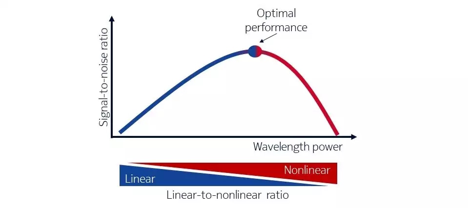
We have known about this behavior since the beginning of the coherent transmission era. We can summarize it with a simple figure: the bell curve of performance, which depicts the trade-off between linear and nonlinear effects in terms of power and transmission quality (for instance, the signal-to-noise ratio). The top of the bell curve represents the sweet spot of maximum performance, which happens only at a given specific ratio between linear and nonlinear effects. That’s much like the focal length in a camera if you think about it.

Bell curve of performance. The optimal power depends on the ratio between linear and nonlinear effects.
To get the most from the network in terms of the capacity and elasticity provided by variable bit rate transponders, we need to monitor the linear-to-nonlinear ratio and ensure that wavelengths operate at optimal power. With new reconfigurable add-drop multiplexers, adjustable frequency grids and innovative modulation formats, automatically monitoring and optimizing performance is becoming simultaneously more complicated and more strategic for maximizing capacity and enabling the self-management of tomorrow's networks. These challenges can be addressed with automation that enables self-monitoring and self-optimization capabilities — something like what autofocus does to keep us from taking blurry pictures.
Until today, we did not have an equivalent to autofocus for power in optical networks. We resorted to intricate mathematical models, approximations and calibrations to ensure that networks would work at a good power level. The result? A static network that always operates "OK" but never optimally. Nokia Bell Labs is working towards redefining optical networking by developing a technique for automating power optimization based on light spectral characteristics.
Zooming in on optical spectral density
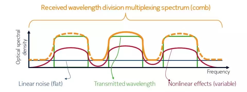
Optical wavelengths travel in the network packed together thanks to wavelength division multiplexing. Optical spectral density is a physical quantity that represents the distribution of power into the frequency components that constitute the transmission. As shown in the figure below, it resembles a comb in which each tooth is a wavelength. At the transmitter, where there are no (or few) impairments, the wavelengths are sharply separated and suffer from no (or little) noise, as shown by the green line. At the receiver, transmission impairments such as linear noise and nonlinear effects combine to distort the transmitted wavelengths and their spectral density, as shown by the orange line. Each received wavelength’s spectral density serves as a fingerprint that indicates the proportion of linear and nonlinear effects that act on the wavelength itself.

The optical spectral density shape depends on the proportion between linear and nonlinear effects.
If we operate on the left of the performance bell curve (i.e., in the linear regime) we will have flat tails at the wavelength's boundary due to the dominance of flat linear noise, as indicated by the blue line. If we operate on the right of the bell curve (i.e., in the nonlinear regime), we will have more rounded tails because of the unique spectral shape of nonlinear effects, as indicated by the red line. Nevertheless, building a formal mathematical body that can correlate the system performance to the spectrum shape is a challenge, especially when some data points are inaccessible. This is because nonlinearities depend on the interplay of numerous factors, including fiber attenuation, the dispersion map and the number of wavelengths operating in the network at a given moment.
Unleashing the power of machine learning
Fortunately, we can simplify things and improve models by turning to machine learning, and to neural networks in particular. Neural networks are algorithms designed to connect raw inputs to target outputs. In this case, the input is the wavelength optical spectral density and the output is the power correction we need to ensure that the wavelength operates at the optimal power.
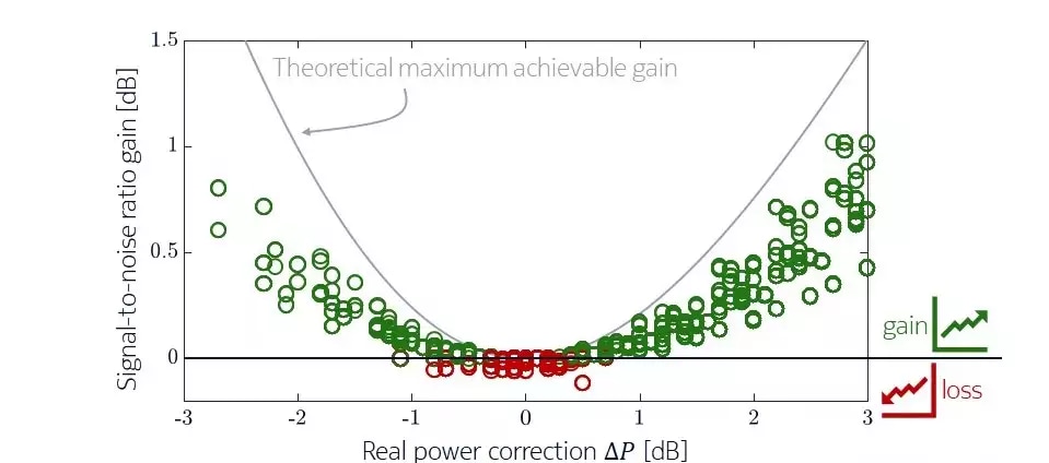
To learn how to connect inputs to targets, neural networks need a lot of training examples. We provided these examples by conducting many experiments. Once the neural network was trained, we began testing it. For example, we provided an optical spectral density of a transmission never seen in the training phase as input, and the algorithm made the optimal power correction. Everything worked smoothly, providing up to 1 dB (25 percent) gain in signal-to-noise ratio in the region around the optimal power and a negligible loss in transmission quality. What this means is that the foundation for automated optical power optimization is finally here. For those who want a deeper view of the technology, all the details can be found in this article.

Power correction training and testing mechanics in brief. We provide the raw spectral density as input (i.e., orange line) and target power correction as output.

Gain in signal-to-noise ratio with automated power correction.
Building on a powerful automation foundation
We have tested automated power correction in the lab and are in the process of testing it in the real world with live data. The algorithm successfully resolves this complex mathematical analysis because it merges the knowledge that can be exploited using real data (i.e., collecting numerous power corrections associated with wavelength spectral density shapes) with reliable and solid physical insights.
For us at Nokia Bell Labs, the biggest reward is developing disruptive research for tomorrow’s communications. Our research into automated power correction has two key impacts:
- Improved network consciousness: Our technique helps make the network aware of its optimal state. Operating at the optimal performance creates a real capacity benefit for deployed systems. Indeed, a fair portion of today’s network capacity is eroded by design margins. Power optimization combined with variable bit rate transponders will unleash the full potential of the optical network by automatically and continuously filling those margins with extra network capacity without requiring punctual manual configurations.
- Optimization through ready-to-use analytics: Today, operating a wavelength at its optimal power is a delicate and challenging job that requires detailed, comprehensive and unique optical network expertise. Soon, thanks to this technique and easy-to-use tools such as Nokia WaveSuite Network Insight applications, we will be able to visualize, correlate and learn so that everyone can benefit from optical power “autofocus” optimization. The democratization of analytics skills starts with solutions like this one.
With this in mind, we’ll see more on these topics with our next posts.
Learn more
- Application note: Insight-driven optical networks: Automating networks with innovative business and network insights
- WaveSuite Network Insight Health & Analytics data sheet
- Web page: Nokia insight-driven optical networks
- Research paper: Experimental investigations on power spectral density estimation in heterogeneous dispersion unmanaged transmissions
- Research paper: Optical nonlinearity monitoring and launch power optimization by artificial neural networks


