Take the automation route to accurately identify optical network fibers

Since the early 2000s, car GPS navigation systems have helped us get where we need to be quickly and efficiently. By using map information, road types and speed limits, they can find an optimal route between locations. But let’s imagine a GPS software company that gets incomplete information about road types and their speed limits. Their software certainly wouldn't be very useful to travelers or self-driving cars.
In an optical network, we face a similar situation when we lose information about the types of optical network fibers that have been deployed. The fiber type is an essential parameter for optical network system design. Many networks are built using different types of fibers, and each fiber type introduces unique optical signal impairments. Having complete knowledge of network fiber types allows us to increase the capacity or availability of the network wavelengths.
But a lack of knowledge of fiber types occurs more often than you might think, especially as non-telecom companies (e.g., stadium operators) build their own infrastructures. Contributing factors include the use of outdated records or erroneous fiber connections during network repair or growth. An operator can also get erroneous information about fiber types when it buys or rents part of its network infrastructure from another operator.
To distinguish between optical fiber types, we can rely on chromatic dispersion, one of the main parameters that differentiates them. Chromatic dispersion is the phenomenon in which the velocity of a wave traveling inside the fiber depends on its frequency.
Benefit of knowing the fiber type
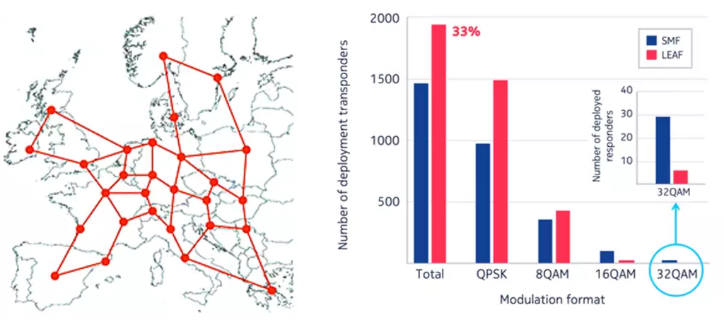
A recent study of a European operator’s backbone network highlights the benefits of knowing exactly what types of fiber have been deployed. The left side of Figure 1 shows a topology that includes 41 fiber links and 28 nodes. Each link is composed of several fiber spans separated by optical amplifiers. We compared the number of transponders needed to fulfill traffic demands when running over an infrastructure made up of either SMF-28® or LEAF® fiber types. The results presented on the right side of Figure 1 show a 33 percent increase in the number of deployed flexible bit rate elastic transponders for a LEAF-based network compared to an SMF-based network. This increase translates into higher CAPEX and network TCO.

Figure 1. A European network operator’s backbone network topology (left) and a comparison of the number of deployed transponders for SMF-based and LEAF-based topologies (right).
How do we identify fiber type today?
The current approach for determining fiber type is a slow, manual fiber optic characterization (FOC) test that involves sending two technicians to each fiber span site. A good FOC team can measure an average of two to three spans per day. The process is extremely time-consuming and costly, especially for a network topology like that shown in Figure 1, which includes a few hundred spans. For each span, the team takes bidirectional measurements with an optical time-domain reflectometer (OTDR) and uses test meter devices to measure end-to-end loss, accumulated chromatic dispersion and its slope over the span. The team must execute these tests when fiber spans are not in service.
To avoid the OPEX required for FOC tests, network operators can allocate extra design margins when they deploy optical wavelengths. When fiber type knowledge is missing or comes from an unreliable source, operators design the network by considering all unknown fibers to be the worst fiber type in terms of propagation impairments (selected among a diversity of fiber types known to be deployed in the same network). However, this causes them to underestimate wavelength signal performance, which means they over-dimension the network and take on additional CAPEX.
The road towards automated fiber type discovery
The Nokia Bell Labs algorithm autonomously and simultaneously determines fiber types by leveraging the chromatic dispersion over all established network wavelength light paths measured by all deployed coherent receivers in the optical network. Let’s come back to our GPS software and speed limit recovery analogy to understand what this means.
Without the knowledge of the road types and their associated speed limits, the GPS software would assume that all roads are the slowest type and overestimate travel time. From this starting point, we could collect the travel times and route details for all drivers traveling in an uncongested road network. We could then use this information to derive the speed limit of each segment of road. A road map with the updated speed limits could allow drivers to plan new itineraries in a more time-efficient way.
The road network analogy allows us to make several associations with fiber networks. The main cities are akin to the nodes of the network. Secondary cities (amplifiers) are located between them with only one road (fiber span) that connects to the main cities. The type of road (fiber type for the span) can be unique or not between two main cities. Each road belongs to a set of road types (fiber types).
In a real optical network, the chromatic dispersion can vary within a given fiber type. For example, dispersion can vary between 16 and 18 ps/nm/km for SMF fibers. The exact value depends on the fiber manufacturer or the moment the fiber was produced. Returning to the road network analogy, the speed limit for a given type of road would vary according to its location in the network: 110–130 km/h for motorways (SMF), 70–90 km/h for rural roads (TL) and 30–50 km/h for urban streets (LEAF).
The optical signal can be viewed as a car that always stays in the same lane (wavelength) as it travels between the main cities (network nodes). For each road type (type of fiber), the speed limit (chromatic dispersion) varies with the lane position (wavelength): it is higher in the rightmost lanes for right-hand traffic countries (higher wavelengths). In left-hand traffic countries, road types would be associated to fibers with a negative chromatic dispersion. We could imagine that speed increases at a rate of 5 km/h/lane as we move towards the fastest lanes, much like linear variation of the dispersion within a wavelength.
In a road network, cars can change lanes during their journey. This change is, of course, not possible for an optical network because the wavelength associated with a given light path is constant from the source to the destination point. A signal propagating inside an optical fiber is like a car without a steering wheel that can only follow the same lane until it reaches its destination. In this sense, a tramway or a train would be the best analogy. Going through an electrical regenerator at the network node would be the only way to change lanes, like with a railroad switch. To evaluate this speed limit variation with the lane position, we need to differentiate all the travel times according to the fixed lane position (wavelength) for each car’s route to its destination (light path).
Nokia Bell Labs has developed an algorithm to solve the problem of identifying fiber types in a very efficient way. The ultimate goal is to derive the speed limit of the central lane (dispersion @1550 nm) and the speed variation with the lane position (dispersion slope @1550 nm) for each road portion (fiber span). The algorithm searches these values in all the different speed limit ranges (one for each road type) so that the expected traveling time corresponds to the ones sent by all cars. For an optical network, we need to list all possible types of fibers and the corresponding range of dispersion (and slope) we can encounter. By combining the travel time of all different road paths (accumulated dispersion per light path), we can deduce the travel time for each road in the network (accumulated dispersion per fiber span) and the ways the time can vary based on lane position (slope with wavelength). We can then evaluate each category of road (fiber type) and its speed limit characteristics (dispersion/dispersion slope).
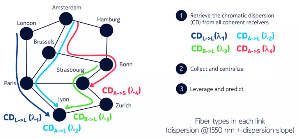
The problem becomes more complex when the road type (fiber type) changes between the main cities of the road network (the nodes of the optical network). Figure 2 presents the different steps of the fiber characterization for a small part of the European network shown in Figure 1:
- We retrieve the chromatic dispersion (CD) accumulated along all light paths, a quantity available in each coherent receiver. The accumulated dispersion is labeled with the wavelength of the corresponding light path. In the example shown in Figure 2, there are four light paths : London➔Lyon, Amsterdam➔Lyon, Bonn➔Lyon and Amsterdam➔Strasbourg.
- We collect and centralize all these CD values {CDL->L (λ1), CDA->L (λ2), CDB->L (λ3), CDA->S (λ4)}.
- We leverage the CD values knowing the network topology and can predict the dispersion and its slope for each fiber span in the network.
We can obtain an accurate recovery speed limit (i.e. dispersion/dispersion slope recovery) once we have sufficient knowledge of the length of each road portion (i.e. each fiber span) and can precisely measure the arrival time of each car (i.e. the accumulated dispersion of each light path).

Figure 2. Illustration of the method for fiber characterization.
Autonomous fiber characterization made easy
Our research shows that the algorithm can be applied to a continent-sized optical network, in this case a European backbone network. We need only collect the accumulated dispersion (CD) of all the established light paths. This information is available for free because it is one of the telemetry outputs of the coherent receiver. There is no need to add more devices. We assume that each individual link contains only one type of fiber.
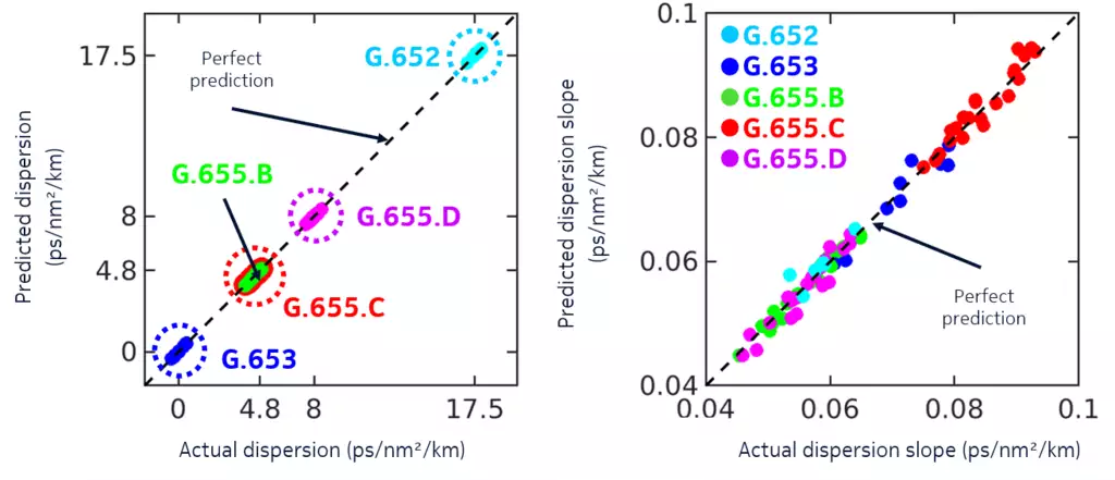
In Figure 3, we show the dispersion and dispersion slope for all 82 unidirectional links in the network. Each color corresponds to one of the five fiber types in the network (G.652, G652, G555.B, G655.C and G.655.D). On the left side of the figure, the predicted dispersion is plotted against the actual value. The right side of the figure shows the predicted versus actual values for the dispersion slope. For a perfect prediction, all points would be strictly aligned on the dashed black line.
Since our algorithm can evaluate the dispersion slope, it can distinguish between fibers that have the same dispersion (G655.B and G655.C with a dispersion around 4.4ps/nm/km) but different dispersion slopes (either ~0.055 or ~0.084 ps/nm2/km). By using this algorithm, we can gain accurate knowledge of fiber types as the network grows without taking portions of it out of service.

Figure 3. Predicted vs actual dispersion (left) and predicted vs actual dispersion slope (right) for all network links. Five categories of fibers have been tested: G.652, G.653, G.655.B, G.655.C and G.655.D.
Clearing the route to better optical network performance
Missing, incomplete or erroneous information about fiber types is a reality of life for optical network operators. But operators don’t have to live with the capacity or availability impairments that these gaps in knowledge can bring. With intelligent tools and algorithms that can accurately identify network fiber types, optical network operators can choose the best route towards optimizing their networks for maximum performance.
Learn more
Application notes
Nokia Insight-driven optical networks
Nokia WaveSuite Network Insight
Data sheet
WaveSuite Network Insight – Health and Analytics


