Beyond faster speeds and more waves - getting the most out of fibers

In my previous blogs, I discussed various ways to improve the data transmission capacity of optical fiber networks given the unrelenting pace at which bandwidth demand is forecast to grow over the next decade (~40 percent/year). In those blogs, I looked at the Shannon Limit, which dictates the data transmission capacity in a physical medium. The nonlinear Shannon equation, C ~ M x B x P x log2(1+SNR) where M= number of spatial paths, B = Bandwidth, P = the number of polarization states used (typically two polarization states), and SNR is the signal-to-noise ratio. Having explored techniques being developed to improve bandwidth and the SNR in previous blogs, in this final blog, I will focus on how the spatial component of the equation, M, can be utilized to enable further increases in total fiber capacity.
Optical fibers are used to guide light transmitted and received at each end of a fiber optic link, and can do so over tens of meters to thousands of kilometers. Since fiber optic cables first started being used by telephone companies in the late 1970s, an estimated 5 billion kms of optical fiber have been deployed around the globe[1], connecting continents, cities, people and enterprises. Optical fiber provides the most reliable form of data transmission, impervious to weather and electromagnetic storms. It also provides the highest capacity and lowest power consumption per bit traveled.
Many types of optical fibers exist, from multi-mode, large area fibers optimized for short distance transmission within buildings and data centers, to single-mode fibers optimized for long-distance transmission. For the purposes of this blog, we will focus on the latter.
How can optical fibers increase network capacity?
Let’s look at high performance fibers used for interconnecting metropolitan areas, countries and continents. These fibers feature a silica doped core with germanium formulation that has very low propagation loss within the C and L bands. They are also single mode fibers (SMF), meaning that the fiber supports a single propagation mode for the light transmitted through it’s core. Various versions of single-mode fiber exist, differing in their dispersion and loss characteristics and are defined by industry standards such ITU-T G.652, G.654, G.655 and others.
So very obviously, one can increase total network capacity simply by using more fibers; increasing the fiber count of cables deployed within cities, along highways, or under oceans. Techniques for increasing the total capacity on a fiber optic link are now diverging, between subsea and terrestrial applications. We’ll start by looking at subsea.
Traditionally subsea fiber cables have been limited to no more than eight fiber pairs due to the challenges imposed when deploying a cable system at the bottom of the ocean, over thousands of kilometers. In that case, the figure of merit (FoM) for fiber pairs was the highest capacity achievable, or spectral efficiency. As we saw in a previous blog, further progress along this FoM is becoming limited, as the technology is now reaching the Shannon limit.
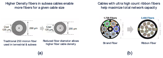
The new generation of subsea cables have managed to increase total capacity, not by increasing capacity per fiber, but by increasing the number of fiber pairs within a cable. So more recently, the FoM is shifting from highest capacity per fiber pair towards total cable capacity. This is achieved by reducing the overall diameter of the individual fibers, thereby making room for additional fibers without increasing the overall subsea cable diameter (Figure 1a). This is an important advance, since the diameter of subsea cables cannot be increased due to operational constraints imposed by the nautical equipment that lays the cable on the ocean floor.
Core terrestrial network cables, in contrast, are not constrained by the size of cable, thus the number of fibers per cable have scaled over time to encapsulate up to 288 fibers, or more. More recently, fiber optic cable suppliers have managed to design and implement cables that utilize high density ribbon fibers rather than conventional stranded fibers, offering operators the ability to significantly increase the number of fibers per cable (Figure 1b). With recent improvements in the technology of fiber cables, operators are now deploying fiber cables with upwards of 3,400 ribbon fibers in a 1.3-inch (33 mm) diameter cable jacket or sheathing. In the future, greater than 7,800 ribbon fibers are anticipated.

Figure 1. Increasing the number of fiber pairs per cable in (a) subsea networks, and (b) metro networks.
While ribbon fibers can scale cable capacity enormously, they incur higher losses than standard fibers, making them less optimal for long-haul networks that must support low-loss transmission over long distances. Ribbon fibers offer a great solution for scaling network capacity in applications such as metro data center interconnection (DCI), which requires the exchange of enormous amounts of data to interconnect ever-larger data centers.
Multi-core fiber
In addition to putting more fibers in a cable, one can also create more cores in a single fiber. A new generation of multi-core fibers offer promising approaches to scaling network capacity using spatial division multiplexing (SDM).
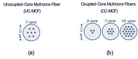
Multi-core fibers (MCF) are single strand optical fibers with a similar diameter (125mm) to other single mode fibers, but where SMF have a singular silica core, MCF, as the name suggests, have multiple. There are two types of MCF: uncoupled core MCF (UC-MCF), and coupled-core MCF (CC-MCF). While in principle the fibers are similar in having multiple cores, in practice the signal propagation characteristics of light through the cores differs significantly (see figure 2a and 2b).
The simplest way to explain the operation of UC-MCF is that it has multiple single-mode cores that are equidistant from one another, yet separated enough to minimize cross talk between them. Simply stated, each individual core acts as an independent fiber channel over which independent data channels are sent, where N is the number of cores within the 125mm diameter (thus 4-core, 7-core, etc.).

Figure 2. Different multi-core fiber configurations
There are several advantages to using uncoupled MCF with existing optical transport technologies. By using an appropriate breakout cable to separate and access the multiple cores within the fiber, it is possible to reuse existing technologies such as coherent transponders, amplifiers, reconfigurable optical add-drop multiplexers (ROADMs) and other systems components.
If an operator has limited duct space for pulling new conventional, single-core fiber cables, they could in the future elect to deploy multi core fiber cables to significantly increase the number of fibers available for transport. While this technology promises to increase total network capacity, further development is needed to enable high-volume manufacturing and validation of network use cases.
In contrast to UC-MCF, the multiple cores in CC-MCF are closely coupled to create cross talk between cores, versus avoiding it. The technical challenge is to “untangle” the data transmission of the different optical data channels transmitted across the multiple cores. Coherent detection at the output of each core is used, followed by joint digital signal processing using MIMO techniques borrowed from wireless networks.
With spatial mode propagation and the use of MIMO, the CC-MCF, behaves as a super high capacity fiber, surpassing what is possible with conventional single-mode fibers. Making CC-MCF a practical reality is aided by the fact that they are much simpler to manufacture than UC-MCF, as the location of each core does not need to be as precise. However, practical implementation must first overcome some engineering challenges, including the development of practical low-power MIMO circuitry.
Hollow-core fiber
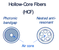
One final fiber technology showing promise is Hollow Core Fiber (HFC). As the name suggests, an HCF fiber has no physical core, and instead relies on a hollow or empty core, filled with air (Figure 3). This reduces the refractive index of the propagation medium through which optical signals travel, from approximately 1.5 for the silica glass used in standard SMF, to approximately 1, for vacuum or air. This increases the effective speed of light by 50%, and makes HCF an attractive solution where the absolute lowest transmission latency is needed.

Figure 3. Structure of different hollow-core fibers
Hollow-core fibers have been discussed in technical papers for over a decade, and there are now several hollow-core fibers available on the market. One example of HCF is the Photonic Bandgap design, which is made of small honeycomb tubes surrounding a hollow core. Unfortunately, the structure is lossy, losing around 4db per km, which makes it unsuitable for typical metro or long-haul networks. Deployments have been limited to low latency high frequency trading use cases.
With the acquisition by Microsoft of an HCF specialist company called Lumenisity , the optical community is closely watching the newest developments of this fiber type, which promises low latency, orders of magnitude improvement in non-linearity, and extended bandwidth spectrum beyond 1700nm. Lumenisity’s new HCF design, called Nested Anti-Resonate Nodeless Design (NAND), has started successful small-scale deployment at the London stock exchange for high frequency trading.
This concludes the third in our series of blogs describing different avenues for increasing optical network capacity, and new innovations that are being explored to enable further scaling into the future. As we have seen, although the Shannon Limit is currently capping progress along one metric, spectral efficiency, there are several paths to further including new spectral bands within optical fibers, and new fiber types with more cores. These innovative techniques and emerging technologies will allow the industry to leverage every dimension of the Shannon equation that should enable us to keep ahead of the curve for the growing bandwidth demands of the future.
References
[1] According to Jacoby, M., “As telecom demands grow, optical fibers will need to level up” in Chemical and Engineering News (Mar 2020), there were roughly 4 billion kms of optical fiber in 2020 with 500 million kms being manufactured per year. By 2023, this would amount to over 5 billion kms of optical fiber. See https://cen.acs.org/materials/photonics/telecom-demands-grow-optical-fi….


